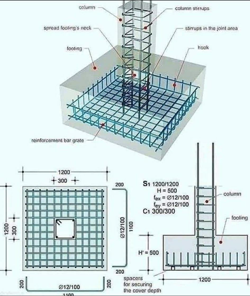
The image displays detailed reinforcement drawings for a concrete column footing. It includes a 3D cutaway view, a top plan view, and a side elevation view, all meticulously labeled with dimensions and reinforcement specifications. Here’s a precise description of each part:
1. 3D Cutaway View (Top):
- Footing: A rectangular concrete block forming the base of the foundation. It is shown partially transparent to reveal the internal reinforcement.
- Reinforcement Bar Grate: A grid of steel reinforcing bars (rebar) embedded within the footing. These bars are arranged in two orthogonal directions to resist tensile stresses.
- The bottom layer of the grate consists of horizontal bars running in one direction.
- The top layer of the grate consists of horizontal bars running perpendicular to the bottom layer, forming a mesh.
- The ends of some of these bars are bent upwards to form hooks, providing better anchorage within the concrete.
- Spread Footing’s Neck: The upper portion of the footing that transitions to the column base.
- Column: A vertical concrete structural element extending upwards from the footing. It contains vertical reinforcing bars.
- Column Stirrups: Horizontal reinforcing bars that wrap around the vertical column bars at regular intervals. These stirrups provide confinement to the concrete core and prevent buckling of the vertical bars.
- Stirrups in the Joint Area: Closer spacing of stirrups is shown in the region where the column meets the footing, indicating higher shear stresses in this area.
- Hook: The bent end of a reinforcing bar, used to improve anchorage within the concrete.
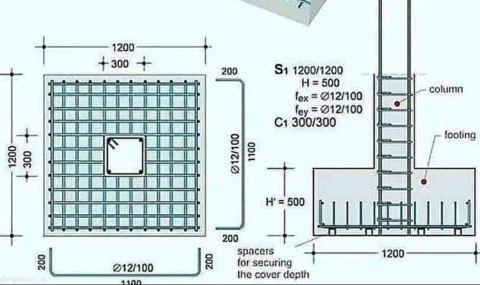
2. Top Plan View (Bottom Left):
- This view shows the layout of the reinforcement bar grate within the footing as seen from above.
- Footing Outline: A square outline representing the top surface of the footing.
- Column Base Outline: A smaller square outline at the center indicating the position of the column.
- Reinforcement Bars: Lines representing the top and bottom layers of reinforcing bars in both directions.
- Dimensions:
- The overall dimension of the footing is indicated as $\(1200 \times 1200\)$ units (likely millimeters).
- The spacing of the reinforcing bars is shown as $\(\emptyset 12 / 100\)$ in both directions, meaning deformed bars with a diameter of 12 units are spaced at 100 units center-to-center.
- Edge distances from the center of the outermost bars to the edge of the footing are indicated as 200 units.
- The dimensions of the central column base are shown.
3. Side Elevation View (Bottom Right):
- This view shows a vertical cross-section of the footing and the lower part of the column.
- Footing: A rectangular shape representing the side of the footing with a height indicated as $\(H = 500\)$ units.
- Column: A vertical element extending upwards from the footing.
- Reinforcement Bars (Footing): Lines representing the side view of the bottom layer of horizontal reinforcing bars. The hooks at the ends of these bars are clearly visible.
- Reinforcement Bars (Column): Vertical lines representing the column’s reinforcing bars.
- Column Stirrups: Horizontal lines at regular intervals representing the stirrups confining the column reinforcement.
- H’: An alternative height dimension for the footing is also labeled as $\(H’ = 500\)$ units.
- Dimensions:
- The horizontal extent of the footing is shown as 1200 units.
- The vertical distance from the bottom of the footing to the top of the reinforcement grate is indicated, influencing the concrete cover.
- Spacers for Securing the Cover Depth: A note indicating the use of spacers to ensure the correct concrete cover for the reinforcement.
- Reinforcement Specifications (S1 and C1):
- S1 1200/1200 H=500: Likely refers to the footing reinforcement specifications for a footing size of 1200×1200 with a height of 500.
- $\(f_{ex} = \emptyset 12 / 100\)$: Reinforcement in the x-direction (likely the longer direction in a rectangular footing, but square here) consists of 12 diameter bars spaced at 100 units.
- $\(f_{ey} = \emptyset 12 / 100\)$: Reinforcement in the y-direction consists of 12 diameter bars spaced at 100 units.
- C1 300/300: Likely refers to the column cross-section dimensions (300×300 units).
- S1 1200/1200 H=500: Likely refers to the footing reinforcement specifications for a footing size of 1200×1200 with a height of 500.
This detailed drawing provides all the necessary information for the proper placement and configuration of the reinforcing steel within the concrete footing and the base of the column, ensuring the structural integrity of the foundation.