This image illustrates the final steps in the process of evacuating an HVAC (Heating, Ventilation, and Air Conditioning) system using a vacuum pump and a manifold gauge set. Evacuation is a crucial procedure performed on refrigeration and air conditioning systems after installation, repair, or when the system has been open to the atmosphere. Its purpose is to remove air, moisture, and other non-condensable gases from the system before refrigerant is introduced. These contaminants can severely impact system performance, efficiency, and longevity. The image provides a visual guide to the correct sequence of actions to ensure a proper and complete evacuation.
Components Shown:
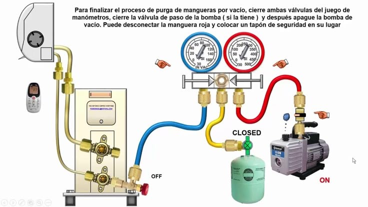
- HVAC System Connection: On the left, a simplified representation of an HVAC system component (likely the service ports of a condenser or evaporator unit) is shown connected via hoses to the manifold gauge set.
- Manifold Gauge Set: This is the central tool in the evacuation process. It consists of two pressure gauges (one for the high side, typically red, and one for the low side, typically blue), a manifold body with control valves, and connections for hoses. The gauges display the pressure within the system and the vacuum achieved during evacuation.
- Vacuum Pump: Located on the right, the vacuum pump is the device responsible for creating the vacuum within the HVAC system. It draws out air and other gases through the manifold gauge set and connected hoses. The image indicates the pump is currently “ON.”
- Refrigerant Cylinder (Optional): A green cylinder labeled “CLOSED” is shown connected to the manifold gauge set via a yellow hose. This cylinder would contain the refrigerant to be charged into the system after the evacuation process is complete. The valve on this cylinder is currently closed, indicating that refrigerant is not being introduced at this stage.
- Hoses: Three colored hoses connect the various components:
- Blue Hose: Typically connected to the low-pressure side of the HVAC system.
- Red Hose: Typically connected to the high-pressure side of the HVAC system.
- Yellow Hose: Usually connected to the vacuum pump during evacuation and to the refrigerant cylinder for charging.
- Control Valves: The manifold gauge set has control valves (handles) that allow the technician to isolate different parts of the system and control the flow of vacuum or refrigerant. The positions of these valves are crucial during the evacuation process.
- Digital Thermometer/Hygrometer (Optional): A small handheld device (likely a digital thermometer and hygrometer) is shown near the HVAC unit. This might be used to monitor ambient temperature and humidity, which can influence the evacuation process.
- Text Instructions (in Spanish): The text at the top provides the crucial steps to follow to finalize the evacuation process.
Step-by-Step Breakdown of the Final Evacuation Procedure (as per the text):
The Spanish text translates to: “To finalize the process of purging hoses by vacuum, close both valves of the manifold gauge set, close the valve of the pump (if it has one), and then turn off the vacuum pump. You can disconnect the red hose and place a safety cap in its place.”
Let’s break down these steps in more detail:
-
Close Both Valves of the Manifold Gauge Set: This is a critical step to isolate the vacuum achieved within the HVAC system from the vacuum pump and the hoses. By closing both the high-side and low-side valves on the manifold, you are essentially sealing off the system under vacuum.
-
Close the Valve of the Pump (if it has one): Some vacuum pumps have an isolation valve at their connection point. Closing this valve further ensures that the vacuum held within the system is not lost when the pump is turned off.
-
Turn Off the Vacuum Pump: Once the system is isolated under a deep vacuum (typically measured in microns), the vacuum pump can be turned off. The image shows the power switch of the vacuum pump in the “ON” position during the evacuation, and this step indicates it should now be switched to “OFF.”
-
Disconnect the Red Hose and Place a Safety Cap in its Place: The red hose is usually connected to the high side of the system. After the vacuum pump is off and the system is isolated, this hose can be carefully disconnected from the manifold gauge set. It’s important to have a safety cap ready to immediately place on the open port of the manifold to prevent any potential loss of vacuum or ingress of air. While the text only mentions capping the red hose connection on the manifold, best practice often involves capping all open ports on the manifold and the service ports on the HVAC system after evacuation.
Why These Steps are Important:
- Holding Vacuum Test: Closing the manifold valves and turning off the pump allows the technician to perform a “vacuum hold test.” If the vacuum level remains stable for a certain period, it indicates that the system is properly sealed and free of leaks. A rising vacuum level suggests a leak that needs to be addressed before charging with refrigerant.
- Preventing Backflow: Closing the pump’s isolation valve (if present) prevents any potential backflow of oil or contaminants from the pump into the evacuated system when the pump is turned off.
- Maintaining System Integrity: Properly capping the hoses and service ports prevents the ingress of atmospheric air and moisture back into the evacuated system, ensuring the integrity of the vacuum achieved.
In summary, this image provides a clear visual representation of the final, crucial steps in the evacuation process of an HVAC system. Following these steps correctly ensures that the system is properly prepared for refrigerant charging by effectively removing non-condensable contaminants and verifying the system’s tightness. The use of the manifold gauge set to isolate the vacuum and the subsequent capping of open connections are essential for maintaining the achieved vacuum and ensuring a successful HVAC system operation.