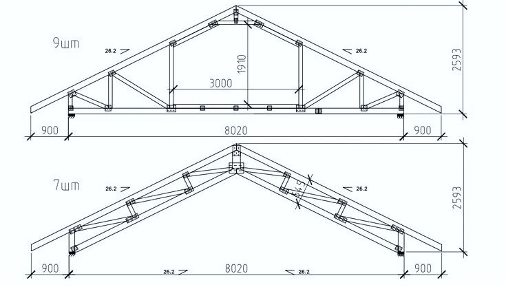
The image shows technical drawings of prefabricated roof trusses. Specifically, it displays three different variations (labeled “2шт,” “9шт,” and “7шт”) of what appears to be the same basic truss design, possibly with slight modifications or internal bracing arrangements.
Here’s a breakdown of the key features visible in the drawings:
- Triangular Structure: Each drawing depicts a truss, which is a structural framework based on triangles. This shape provides inherent stability and strength for spanning distances.
- Top Chords: The sloping members forming the roof’s pitch. The angle of the pitch is indicated as 26.2 degrees.
- Bottom Chord: The horizontal member at the base of the truss, which often acts as a ceiling joist.
- Web Members: The internal diagonal and vertical members that connect the top and bottom chords. These members distribute loads and prevent the chords from buckling. The arrangement and number of web members vary slightly between the three truss variations.
- King Post or Similar Vertical Member: In the “9шт” truss, a central vertical member (king post) is clearly visible, extending from the apex to the bottom chord. The length of this member is dimensioned as 1970 and the height from the bottom chord to the apex is 3000.

- Support Points: The drawings show the truss resting on supports at its ends. The distance from the end of the bottom chord to the support is dimensioned as 900.
- Span: The total span of the truss, the horizontal distance between the supports, is dimensioned as 8020.
- Overall Height: The total height of the truss from the bottom chord to the apex is dimensioned as 2593.
- Labels: Each truss is labeled with a quantity (“2шт,” “9шт,” “7шт”), likely indicating the number of that specific truss type required in a project.
These drawings provide essential information for the manufacturing and installation of these roof trusses, including their geometry, dimensions, and the arrangement of their structural members. They are typical examples of technical documentation used in construction and structural engineering.