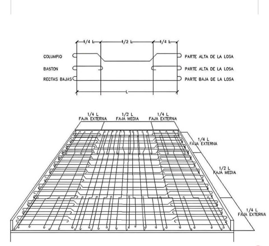
This image displays detailed reinforcement drawings for a two-way concrete slab. Two-way slabs are structural elements in buildings where the load is transferred in both orthogonal directions to the supporting beams or columns. This requires a specific arrangement of reinforcing steel bars (rebar) to handle the biaxial bending moments and shear forces. The image provides both a schematic representation of the bar placement and a perspective view of the rebar cage within the slab.
Top Section: Schematic Bar Placement
The top part of the image shows a simplified, elevational view illustrating the typical placement of different types of reinforcing bars across the span (L) of the two-way slab. The span is divided into quarters (1/4 L) and halves (1/2 L) to indicate the zones where different bar lengths and configurations are used. The labels in Spanish provide further information:
- COLUMPIO: This translates to “swing” or “bent-up” bar. These bars are typically placed to resist negative bending moments (tension at the top of the slab) over supports and positive bending moments (tension at the bottom of the slab) in the mid-span. They are bent upwards near the supports and downwards in the middle. The schematic shows these bars extending from the support towards the mid-span and then bending up.
- BASTON: This translates to “cane” or “straight” bar (often with hooks). These are typically shorter bars placed to primarily resist either positive or negative bending moments in specific regions. The schematic shows a “baston” placed at the top of the slab, likely over a support to resist negative moment.
- RECTAS BAJAS: This translates to “straight bottom” bars. These are straight bars placed near the bottom of the slab to resist positive bending moments in the mid-span. The schematic shows these bars running continuously along the bottom of the slab.
- PARTE ALTA DE LA LOSA: This translates to “top part of the slab.” This label indicates that the “columpio” and one “baston” are located near the top surface of the slab in certain regions.
- PARTE BAJA DE LA LOSA: This translates to “bottom part of the slab.” This label indicates that the “rectas bajas” are located near the bottom surface of the slab.
The horizontal lines represent the different layers of reinforcement within the slab. The varying lengths and bending of the bars are crucial for resisting the complex stress distribution in a two-way slab.
Bottom Section: Perspective View of Reinforcement Cage
The bottom part of the image provides a three-dimensional perspective view of the reinforcing steel bars placed within the formwork of the two-way slab before the concrete is poured. This view helps visualize how the different types of bars are arranged in both horizontal directions. The labels indicate different zones across the slab’s width, similar to the length divisions in the top schematic:
- 1/4 L FAJA EXTERNA: This translates to “1/4 L Outer Band” or “Edge Strip.” These are the regions near the edges of the slab, spanning one-quarter of the total length (L) from each support. These zones often require specific reinforcement detailing due to edge effects and potential shear concentrations.
- 1/2 L FAJA MEDIA: This translates to “1/2 L Middle Band” or “Middle Strip.” This is the central region of the slab, spanning one-half of the total length (L). The reinforcement in this zone is primarily designed to resist the maximum positive bending moments.
The perspective view shows a grid of reinforcing bars running in both orthogonal directions. You can observe:
- Bottom Reinforcement: Straight bars running along the bottom of the slab in both directions, corresponding to the “rectas bajas.”
- Top Reinforcement: Bent-up bars (“columpio”) that start near the bottom in the mid-span and bend upwards towards the supports, providing reinforcement at the top over the supports. Shorter straight bars (“baston”) are also visible near the top over the supports.
- Overlapping Bars: The bars are shown overlapping at certain points to ensure continuous transfer of stress throughout the slab.
- Support Conditions: The edges of the slab are shown resting on supports (likely beams or walls). The reinforcement detailing near the supports is critical for shear resistance and anchorage of the bars.
- Spacing: While not explicitly dimensioned, the bars are shown with a certain spacing, which is determined by the design requirements based on the applied loads and the concrete strength.
Interpretation:
The reinforcement in a two-way slab is more complex than in a one-way slab because it needs to resist bending in both directions. The “columpio” bars are particularly important as they act as both bottom reinforcement in the span and top reinforcement over the supports, efficiently resisting both positive and negative bending moments. The “baston” bars supplement the negative moment resistance over the supports. The “rectas bajas” primarily handle the positive moment in the central span.
The division of the slab into “fajas” (bands or strips) is a common approach in two-way slab design and analysis. The reinforcement requirements can vary between the outer and middle strips due to different moment and shear demands.
In conclusion, this image provides a visual understanding of the intricate reinforcement detailing required for a two-way concrete slab. The schematic and perspective views, along with the labels, illustrate the types of reinforcing bars used and their placement to effectively resist the biaxial bending and shear forces inherent in this type of structural element. This detailed reinforcement is crucial for ensuring the strength, stability, and load-carrying capacity of the concrete slab.