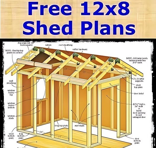
The details presented in the “Free 12×8 Shed Plans” image. This exploded diagram provides a good overview of the basic construction stages and components involved in building a small, rectangular shed with dimensions of 12 feet by 8 feet.
1. Foundation:
- Skids (or Runners): At the very bottom, long horizontal timbers labeled “long floor edge” and “long floor edge” are visible. These are the skids or runners upon which the entire shed structure will rest. They elevate the shed slightly off the ground, providing some protection from moisture and allowing for potential relocation.
- Floor Joists: Perpendicular to the skids are the “floor joists,” typically spaced at regular intervals (often 16 or 24 inches on center, though not explicitly stated). These horizontal framing members provide support for the floor sheathing.
- Blocking (or Bridging): Smaller pieces of wood are shown between the floor joists. These are blocking or bridging, which add rigidity to the floor frame and help prevent the joists from twisting.
- Support Blocks (Potentially Concrete Blocks): Underneath the skids, rectangular blocks labeled “cement pier blocks” or similar are shown. These are likely concrete blocks or pier blocks used to level and further support the skids and the entire shed structure. The spacing of these blocks is important for stability.
- Floor Sheathing: Above the floor joists, a layer of plywood or oriented strand board (OSB) labeled “floor sheathing” forms the solid base or floor of the shed.
2. Walls:
- Wall Framing: The diagram shows the wall framing for at least one of the longer (12-foot) walls. This consists of:
- Wall Studs: Vertical framing members spaced at regular intervals (again, typically 16 or 24 inches on center). These provide the main vertical support for the walls.
- Top Plate(s): Horizontal members running along the top of the wall studs, tying them together and providing a surface for the roof structure to rest upon. The diagram shows “double top plate” which adds strength.
- Bottom Plate (or Sill Plate): A horizontal member at the bottom of the wall studs, attached to the floor sheathing. It provides a base for the wall framing.
- Door Opening: An opening framed with additional vertical members (door jamb studs) and a horizontal header to support the load above the door.
- Window Opening: Similarly, an opening framed for a window with jamb studs and a header.
- Wall Sheathing: The light-colored panels attached to the wall framing are the “wall sheathing” (likely plywood or OSB). This provides structural rigidity to the walls and a surface for attaching the exterior siding.
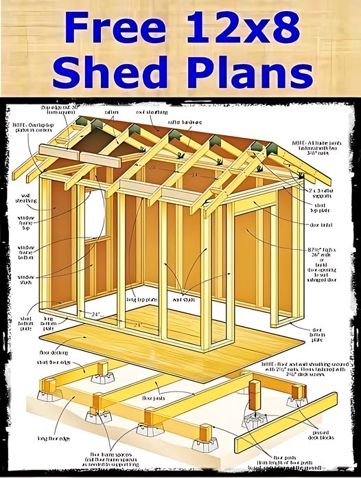
3. Roof Structure:
- Rafters: Angled framing members that form the slope of the roof. They run from the top plate of the walls up to the ridge board. The diagram shows multiple rafters spaced along the length of the shed.
- Ridge Board: A horizontal member running along the peak of the roof, to which the tops of the rafters are attached.
- Collar Ties (or Rafter Ties): Horizontal members connecting opposing rafters at a certain height. These help prevent the walls from spreading outward under the weight of the roof.
- Overhang: The rafters extend slightly beyond the wall framing, creating an overhang that helps protect the walls from rain and sun. The diagram labels “roof overhang.”
4. Other Elements:
- Exterior Siding: Although not fully shown as applied, the presence of wall sheathing indicates that an exterior siding material (like wood, vinyl, or metal) would be attached to it for weather protection and aesthetics.
- Roofing: Similarly, the roof rafters and sheathing (implied) would be covered with a roofing material (like shingles or metal panels) for weatherproofing.
- Fascia: A horizontal board running along the eaves (the lower edge of the roof), often used to attach gutters. The diagram labels “fascia.”
- Soffit: The underside of the roof overhang. The diagram labels “soffit.”
- Trim: Various trim pieces would likely be used to finish edges around doors, windows, and the roof.
Overall Construction Sequence (Inferred):
The exploded view suggests a typical construction sequence:
- Build the foundation (skids and support blocks).
- Construct the floor frame (joists and blocking) and attach the floor sheathing.
- Frame the walls (studs, plates, and openings) on the floor.
- Erect and secure the wall frames to the floor.
- Install wall sheathing.
- Construct and attach the roof rafters and ridge board.
- Install collar ties.
- Apply roof sheathing (not explicitly shown but necessary).
- Install fascia and soffit.
- Apply roofing material.
- Install exterior siding.
- Install doors and windows.
- Add trim and other finishing details.
Key Takeaways from the Diagram:
- The shed is a simple gable roof design (two sloping roof surfaces meeting at a ridge).
- It utilizes standard lumber framing techniques.
- A basic foundation of skids and potentially concrete blocks is used.
- Openings for a single door and at least one window are included in the wall framing.
This exploded diagram provides a fundamental understanding of the components and construction of a 12×8 shed. Actual detailed plans would include precise measurements, lumber sizes, fastening schedules, and more specific instructions for each stage of the building process.