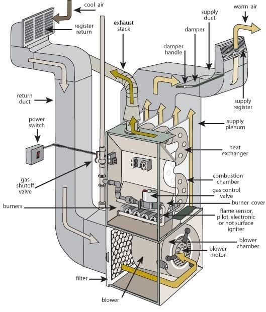
This image provides a detailed diagram of a forced air gas furnace system, illustrating its components and how it functions to heat a building. Here’s a breakdown of the key elements and the airflow:
1. Air Intake and Return:
- Register Return: Cool air from the building is drawn into the system through one or more register returns.
- Return Duct: The cool air travels through the return duct towards the furnace.
- Filter: Before entering the furnace, the return air passes through an air filter to remove dust, pollen, and other airborne particles, protecting the furnace components and improving air quality.
2. Furnace Unit:
- Blower Chamber: The filtered cool air enters the blower chamber located at the bottom of the furnace.
- Blower: A blower (driven by a blower motor) forces the cool air upwards through the furnace.
- Burners: Natural gas (or propane) is supplied to the burners through a gas shutoff valve and a gas control valve.
- Combustion Chamber: The burners ignite the gas within the combustion chamber, producing heat.
- Heat Exchanger: The hot combustion gases flow through the heat exchanger, a series of metal tubes or coils. The air being forced through the furnace by the blower passes over the outside surfaces of the heat exchanger, absorbing the heat without mixing with the combustion gases.
- Flame Sensor, Pilot, Electronic, or Hot Surface Igniter: This component is responsible for safely igniting the gas at the burners. Older systems might use a pilot light, while newer systems typically use electronic or hot surface igniters and a flame sensor to ensure the flame is present.
- Burner Cover: Encloses the burner and combustion chamber area.
- Exhaust Stack: The cooled combustion gases are vented safely outside the building through the exhaust stack.
3. Heated Air Distribution:
- Supply Plenum: The warm air heated by the heat exchanger enters the supply plenum, a distribution chamber located above the furnace.
- Supply Duct: The warm air is then forced through a network of supply ducts that run throughout the building.
- Damper: A damper (controlled by a damper handle) may be present in the supply duct to regulate airflow to different zones or areas of the building.
- Supply Register: The warm air enters the rooms through supply registers or vents.
4. Controls and Safety:
- Power Switch: Allows for turning the entire furnace system on or off.
Airflow Summary:
- Cool air is drawn from the building through the register return and return duct.
- The air is filtered by the filter.
- The blower forces the filtered air upwards through the furnace.
- The air passes over the heat exchanger, where it is warmed by the heat produced in the combustion chamber.
- The warm air enters the supply plenum and is distributed through the supply ducts to the supply registers.
- Cooled combustion gases are expelled outside through the exhaust stack.
This diagram illustrates a typical forced air gas furnace system, which is a common method for heating residential and commercial buildings. The system relies on the efficient transfer of heat from burning gas to the circulating air, which is then distributed throughout the space.